

Schematic Capture
Multi-level hierarchical schematics
DipTrace Schematic Capture is a professional multi-sheet, multi-level hierarchical design environment for circuits of any structure and size. Electrical rule checking validates connections against configurable rules as the schematic develops, and the built-in SPICE simulator analyzes analog, digital and mixed-signal circuits with behavioral model support, so a design is verified before it reaches layout. Circuits convert directly to PCB Layout, accept back annotation from the board, and exchange data with Altium, OrCAD, PADS, P-CAD, Eagle, KiCad and standard netlist formats. Cross-module management keeps the schematic, the board and the component libraries consistent as engineering changes move through a project.

Schematic provides
the following features

Connectivity
Connect component pins visually with wires and buses, or logically without wires through net ports, bus ports and net names. Connectivity carries into PCB Layout, where nets are organized into classes for the design rule system.

Multi-level hierarchy
DipTrace hierarchical schematic is based on a multi-sheet circuit structure. Hierarchical blocks can be inserted into the main sheet or into each other as many times as needed. Hierarchy verification reports loop structures if present.

Analog and digital simulator
The built-in SPICE simulator provides comprehensive analysis of analog, digital, and hybrid circuits. The behavioral model support enables the simulation of complex devices, ensuring more accurate and flexible design validation.
Connectivity
Connect component pins visually with wires and buses, or logically without wires through net ports, bus ports and net names. Connectivity carries into PCB Layout, where nets are organized into classes for the design rule system.
Multi-level hierarchy
DipTrace hierarchical schematic is based on a multi-sheet circuit structure. Hierarchical blocks can be inserted into the main sheet or into each other as many times as needed. Hierarchy verification reports loop structures if present.
Analog and digital simulator
The built-in SPICE simulator provides comprehensive analysis of analog, digital, and hybrid circuits. The behavioral model support enables the simulation of complex devices, ensuring more accurate and flexible design validation.

Electrical rule check
ERC helps to ensure that engineer works in the error-free design environment. Electrical Rule Check with detailed customization reports short circuits, superimposing and unconnected pins, one-pin nets, and checks connections by pin types.

Import / export
Schematic capture module allows for exchanging schematics and drawings with other EDA / CAD packages (Altium, Eagle, P-CAD, PADS, OrCAD, KiCad, DXF, PDF). Support of Accel, Allegro, Mentor, OrCAD, PADS, P‑CAD, KiCad, Protel, Tango, Spice netlists.
Electrical rule check
ERC helps to ensure that engineer works in the error-free design environment. Electrical Rule Check with detailed customization reports short circuits, superimposing and unconnected pins, one-pin nets, and checks connections by pin types.
Import / export
Schematic capture module allows for exchanging schematics and drawings with other EDA / CAD packages (Altium, Eagle, P-CAD, PADS, OrCAD, KiCad, DXF, PDF). Support of Accel, Allegro, Mentor, OrCAD, PADS, P‑CAD, KiCad, Protel, Tango, Spice netlists.
Native XML for Git workflows
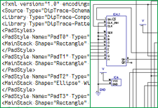
Schematics are stored in native XML, a text-based format suitable for Git, Mercurial and other external version control systems. Version control is provided by the repository, not by DipTrace.
Native XML for Git workflows
Schematics are stored in native XML, a text-based format suitable for Git, Mercurial and other external version control systems. Version control is provided by the repository, not by DipTrace.